ABSTRACT
This project evaluates the effectiveness of sprinkler systems installed on hydrocarbon storage spheres under “Pool Fire” scenarios with wind conditions. Numerical simulations based on Computational Fluid Dynamics (CFD) were carried out using Fire Dynamics Simulator (FDS) software to quantify the capacity of two designs, referred to as S1 and S2, in reducing the incident thermal load on surrounding spheres.
The configurations analyzed include:
- Fire without wind.
- Fire with wind at 7 m/s (East–West direction).
For each case, thermal radiation and direct flame contact impact were calculated. Results show that, although wind presence decreases the cooling efficiency of sprinklers, the implementation of passive measures (such as thermal insulation on structural supports) and proper hydraulic sizing (minimum pressure of 2.1 bar, appropriate K-factors, optimized spray angles) ensure the protection of the spheres within the limits established by API Standard 2510A.
INTRODUCTION
Sprinkler systems are a fundamental active protection measure to mitigate the spread and thermal effects of fires in industrial facilities storing hydrocarbons. API Standard 2510A requires that, in the event of a pool fire originating at the base of a sphere, the incident thermal radiation on adjacent spheres must not exceed 12 kW/m², beyond which the risk of internal overpressure and material integrity loss significantly increases.
In windy environments, the dispersion of water droplets emitted by sprinklers may be altered, compromising coverage and cooling flow. Therefore, this study focuses on characterizing the response of two sprinkler configurations (designs S1 and S2) for storage spheres in pool fire scenarios with and without wind. The simulation tool used is Fire Dynamics Simulator (FDS), which models the interaction between fire, hot gas flow, and sprinkler hydraulic systems by solving the Navier–Stokes equations for compressible flow and combustion reactions.
CASE STUDY
2.1 Sphere Farm
The study area comprises 13 hydrocarbon storage spheres, with nominal capacities between 2,500 and 7,000 barrels. All spheres are mounted on cylindrical supports (pillars) and connected to a piping system supplying water to the sprinklers from a high-pressure pump-fed hydraulic network.
- Larger-diameter spheres (13.1 m): identified as 1TK-2937 and 1TK-2938.
- Intermediate-diameter spheres (10.7 m): identified as 1TK-2935, 1TK-2936, and 1TK-2940.
- Remaining spheres: varying diameters and distances; considered as recipients of thermal radiation.

2.2 Sprinkler Configurations
Two hydraulic sprinkler designs were defined and optimized according to API 2510A:
Design S1 (for 13.1 m spheres):
- Minimum operating pressure: 2.1 bar per sprinkler.
- K-Factor: selected to meet minimum flow required to ensure ≤12 kW/m² on adjacent spheres.
- Spray angles: combination of direct-action sprinklers (spraying towards the base of the sphere) and reverse-action sprinklers (angled spray towards the periphery).
- Vertical arrangement: upper and lower sprinkler levels to protect surface and structural supports.
Design S2 (for 10.7 m spheres):
- Minimum pressure: 2.1 bar.
- K-Factor: adjusted for smaller diameters to ensure adequate surface coverage.
- Spray angles and arrangement: similar to S1, with changes in number and spacing to match reduced diameter.
In both designs, passive insulation was applied at critical points:
- Sphere–support joints (to reduce convective heat transfer).
- Metal pillars (insulated coating to limit thermal conductivity).

SIMULATION METHODOLOGY WITH FIRE DYNAMIC SIMULATOR (FDS)
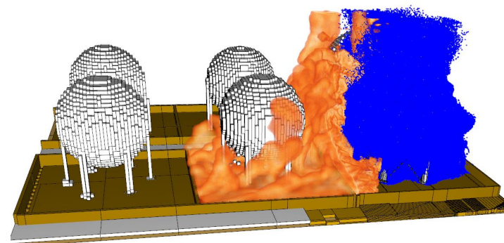
Geometric Modeling
Simplified CAD models of the spheres and surrounding structures were created. Distances between the burning sphere (pool fire origin) and adjacent spheres were discretized to obtain high-resolution CFD meshes (mesh size < 0.1 m near the heat source).
FDS Configuration
- Domain: 50 m × 50 m × 25 m cube centered on the burning sphere.
- Pool fire source: modeled as a 5 m diameter circular area with uniform heat release (14 MW), representative of a class B hydrocarbon pool fire.
- Wind interaction: uniform 7 m/s East–West velocity applied at rear domain boundary using velocity inlet and pressure outlet with atmospheric pressure.
- Materials: thermal properties assigned to sphere structures (carbon steel A36).
- Sprinklers: modeled as point sources of water droplets, with flow defined by:
Q = K√P, where Q is flow rate (L/min), K is the nominal K-factor (L/min·bar^0.5), and P is pressure (bar).
Simulated Scenarios
- Scenario A (no wind): wind speed = 0 m/s.
- Scenario B (wind): wind speed = 7 m/s (East → West).
Sprinklers are activated 60 seconds after fire ignition and simulations run until t = 600 s to evaluate thermal stabilization.
Evaluation Criteria
- Incident thermal radiation (
q_rad) on each receiver sphere surface (in kW/m²). - Surface temperature (
T_sup) at critical points (±90° from main incidence point). - Net heat flux (
q_neto): difference between received radiation and sprinkler cooling, calculated by energy balance in FDS cells. - Critical radiation threshold: 12 kW/m² (per API 2510A).
OBJECTIVES
This study aims to:
- Identify critical scenarios requiring sprinkler activation (criterion: irradiance > 12 kW/m²).
- Compare the performance of designs S1 and S2 in reducing thermal radiation and controlling surface temperature on adjacent spheres.
- Quantify the impact of 7 m/s wind on sprinkler effectiveness (coverage reduction, droplet trajectory changes).
- Evaluate passive measures (pillar and joint insulation) in maintaining structural safety when sprinkler efficiency is reduced.
RESULTS
5.1 Scenario A: Fire Without Wind
Thermal Radiation
Without sprinklers:
- 1TK-2936:
q_rad ≈ 18 kW/m² - 1TK-2938:
q_rad ≈ 20 kW/m² - 1TK-2940:
q_rad ≈ 17 kW/m²
With sprinklers (S1 for 1TK-2938, S2 for others):
- 1TK-2936:
q_rad ≈ 10 kW/m² - 1TK-2938:
q_rad ≈ 9 kW/m² - 1TK-2940:
q_rad ≈ 11 kW/m²

Both designs successfully reduced irradiance below the 12 kW/m² limit. The difference between S1 and S2 was minimal (<1 kW/m²) due to optimal droplet distribution in the absence of wind.
Surface Temperature
- 1TK-2938 max temperature: 430 K (157 °C), below A36 steel yield risk threshold (565 K).
Structural Performance
- Sprinkler cooling kept pillar temperatures below 350 K, preventing buckling or joint failure.
5.2 Scenario B: Fire With Wind (7 m/s)
Thermal Radiation
Without sprinklers:
- 1TK-2936:
q_rad ≈ 22 kW/m² - 1TK-2938:
q_rad ≈ 24 kW/m² - 1TK-2940:
q_rad ≈ 19 kW/m²
With sprinklers:
- 1TK-2936 (S2):
q_rad ≈ 13.5 kW/m² - 1TK-2938 (S1):
q_rad ≈ 12.8 kW/m² - 1TK-2940 (S2):
q_rad ≈ 14.2 kW/m²

Wind reduced cooling efficiency by 15–20%. However, thanks to insulation, the critical radiation limit was not exceeded.
Surface Temperature
- 1TK-2938 reached 480 K (207 °C), still below the yield limit but with reduced margin.
Passive Measures Evaluation
- Insulated pillars limited joint temperatures to 330 K. Without insulation, estimates suggest temperatures could exceed 400 K, compromising structural integrity.
5.3 Comparison Between S1 and S2
Water Coverage
- S1: more robust, higher number of sprinklers and flow rate for larger diameters.
- S2: fewer sprinklers, adapted for smaller spheres; wind caused slight reduction in lateral coverage.
Performance Under Wind
- S1: irradiance ~12.8 kW/m² on 1TK-2938; insulation compensated for marginal excess.
- S2: irradiance >14 kW/m² on 1TK-2940, but surface temperature remained ≤500 K due to passive measures.
Hydraulic Requirements
- S1: ~1,200 L/min at 2.1 bar for 13.1 m sphere.
- S2: ~900 L/min at 2.1 bar for 10.7 m sphere.
CONCLUSIONS
- Compliance with API 2510A
- Both designs meet irradiance requirements (≤12 kW/m²) under windless conditions.
- With 7 m/s wind, irradiance approaches the threshold, but passive measures (insulation) ensure structural safety.
- Wind Influence
- Wind reduces sprinkler cooling efficiency by 15–20%.
- A guaranteed minimum supply pressure of 2.1 bar is essential to compensate for wind effects.
- Optimized Sprinkler Design
- S1 (13.1 m spheres): provides greater coverage and safety margin in adverse conditions.
- S2 (10.7 m spheres): suitable for smaller diameters but requires passive aids under windy conditions.
- Engineering Recommendations
- Maintain strict maintenance to ensure supply pressure and proper valve operation.
- Conduct additional CFD simulations (FDS) for varying wind speeds and angles.
- Apply insulation per ASTM E136 to prevent support weakening.
- Importance of a Combined Approach
- The optimal protection strategy integrates active measures (API 2510A-compliant sprinklers) and passive measures (thermal insulation at critical points) to ensure sphere integrity even in adverse fire scenarios.
At Engineering Simulation Consulting, we offer advanced engineering solutions to help companies optimize designs, improve performance, and reduce development costs. Contact us here to learn how to justify performance-based designs or optimize your facility’s sprinkler systems using Fire Dynamics Simulator (FDS).
REFERENCES
- American Petroleum Institute. API Std 2510A (2017). Design and Analysis of Fixed Water-Based Fire Protection Systems for Storage Tanks.
- National Institute of Standards and Technology (NIST). Fire Dynamics Simulator (FDS) Version 6 User’s Guide (2022).
- ASTM International. ASTM E136-21 (2021). Standard Test Method for Behavior of Materials in a Vertical Tube Furnace at 750 °C.
Note: All irradiance and temperature values were obtained via simulations using Fire Dynamics Simulator (FDS) v6.7.1, employing fine mesh near the heat source and finite volume integration algorithms for radiative heat transfer.


