ABSTRACT
This article focuses on finite element analysis of electronic components, presenting various simulations of the mechanical functionality of a Raspberry Pi 4, focusing on a global perspective of the case design with ventilation slots. The study aims to improve processor cooling, impact resistance, and assembly. Two case geometries are evaluated: the initial geometry (GV-1) shows good impact resistance but issues with cooling, while the modified geometry (GV-2) improves cooling but presents a risk of breakage under impact.
INTRODUCTION
What does finite element analysis (FEA) currently offer engineers and designers? Undoubtedly, the ability to virtually evaluate and refine a product before manufacturing: optimizing design, selecting materials, analyzing stresses and deformations to meet standards, and enhancing durability.
Centralizing all simulations that affect a product’s design and functionality within a single engineering or decision-making hub minimizes the number of optimization loops, evaluates the accepted design globally, and reduces the risk of counterproductive changes. Decisions regarding stiffness (mechanical simulation), manufacturing (rheological simulation, as in this case), or heat dissipation (CFD simulation) are made from a unified perspective, understanding their reciprocal implications.
CASE STUDY
The case study evaluates the design of a case with a ventilation system for a Raspberry Pi 4 (a small, versatile, and low-cost computer used in a wide range of applications).

The initial case design, referred to as GV-1, has the following features:
- Top cover with 1.5 mm slots and 1.5 mm thickness.
- Bottom cover of 1.5 mm.
- Perforated cover of 1.5 mm.
- Screwed connection between the bottom and top covers. Ventilated cover secured with a snap-fit connection.
OBJECTIVES
The finite element analysis aims to answer the following questions:
Is the ventilation system functioning adequately? Is the proposed injection system feasible or optimal to ensure the product’s aesthetic and mechanical quality? From the perspective of the dynamic load specification and impact tests, is the design acceptable?
Thus, the product’s objectives are:
- A case with a flawless surface finish manufacturable via thermoplastic injection molding (PC-ABS).
- Resistance to drops and impacts.
- A cooling system and design that ensure functionality standards (processor temperature < 68°C).
- Simple assembly.
RESULTS
The first simulation conducted was a CFD simulation to assess the processor temperature. However, as observed, the initial geometry (GV-1) slightly exceeds the processor’s maximum target temperature.

To address this issue, the dimensions of the ventilation slots were increased, reducing the thickness between slots to 1 mm (geometry GV-2).
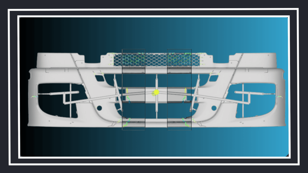
This change in the case geometry raised two design questions: Will this modification cause issues during injection? Will the slots be rigid enough to withstand an impact without breaking? To resolve these concerns, a preliminary rheological analysis was conducted to identify filling problems and the location and quality of weld lines, which would affect structural results. Additionally, a dynamic impact analysis was performed on the slot area.

The results indicated that the GV-2 geometry exhibited cold weld lines, implying a risk of breakage under impact (lower resistance), while the initial GV-1 geometry offered better conditions. This was confirmed through an impact simulation, showing that the GV-2 geometry had an aggravated risk of breakage due to the weld lines.
After simulating the injection of the covers and conducting the impact analysis, it was concluded that the GV-2 geometry, which met the cooling objectives (processor temperature < 68°C), presented weld line issues in the slots due to reduced flow front velocity in these areas. These lines weakened the already narrow slot section. On the other hand, the initial GV-1 geometry showed acceptable filling and impact performance, although it posed a risk of plastic deformation in the slots but not breakage. This means reducing the slot thickness is not viable. At this point, it would be advisable to evaluate the possibility of changing the fan or its operating point (e.g., rotation speed).
Finally, a validation of the assembly system using clips was conducted, including insertion/extraction tests and an analysis of the risk of disassembly upon impact.
The clipping process was found to be feasible, meeting insertion and extraction force requirements, although there was a risk of disassembly in drop tests. The option of a screwed connection was proposed, depending on the product’s cost and range, to secure the assembly against this test.
CONCLUSIONS
The interconnection and dependency of all finite element simulations are unavoidable. The fundamental variables (design and material) are common across them, and decision-making must also be unified. Within the space of plausible solutions that meet the predefined technical and economic standards, only a centralized management approach for product development and simulations will allow for the selection of the optimal design.
At Engineering Simulation Consulting, we provide advanced engineering solutions to help businesses optimize their designs, improve product performance, and reduce development costs. Contact us here for more information on how to design using finite element analysis of electronic components.