Abstract
This study presents a Computational Fluid Dynamics (CFD) analysis of a limestone filter manifold used in a desalination plant. The main objective is to optimize the geometric design of the manifold to ensure a uniform flow distribution among the different collectors, under both nominal and backwash conditions. By varying the internal dimensions of the branches, a substantial improvement was observed in the flow homogeneity and in the stability of the pressure distribution, with deviations below 3% in all simulated cases.
Introduction
The hydraulic design of components in a desalination plant must prioritize energy efficiency, operational reliability, and ease of maintenance. In this context, CFD simulations provide a powerful tool for predicting flow behavior in complex geometric configurations, such as filters, manifolds, or distribution channels, enabling the identification of turbulence zones, excessive head losses, and flow imbalances that could compromise system performance.
This study applies an advanced CFD model to analyze the hydraulic behavior of a limestone filter—an essential component in the remineralization stage of treated water—with the aim of evaluating its performance and proposing design improvements.
Case Study
The case study involves a large-scale limestone filter integrated into a desalination plant. The system consists of a main manifold from which multiple collectors branch out radially. The initial configuration showed significant flow imbalances: the first collectors received flows up to three times higher than the average, while the last collectors were underfed.

Objectives of the CFD Analysis
The specific objectives of the CFD analysis were as follows:
- Achieve uniform flow distribution among the collectors (maximum deviation from the average <10%).
- Evaluate head losses under nominal and backwash operating conditions.
- Identify critical hydraulic phenomena such as vortices, recirculation zones, or stagnation areas.
- Optimize the geometry of the manifold branches to minimize flow variability.
Methodology and Simulation Conditions
General conditions of the CFD model:
- Fluid: Water at 20 °C (ρ = 1000 kg/m³; μ = 0.001002 kg/m·s).
- Computational mesh: 61.3 million elements, 10.5 million nodes.
- Symmetry conditions applied to reduce the domain.
- Boundary conditions: Constant inlet flow, 42 outlets with reference pressure, sliding surfaces at the ends.
Results
Initial Configuration (Uniform Diameter of 102 mm)
The analysis of the initial configuration revealed a highly non-uniform flow distribution. Several nozzles exhibited flows significantly below average, while others exceeded the average by more than 100%. Collector C2 was identified as having the greatest negative deviation.

Optimized Configuration (Adjusted Diameters)
After a series of iterations, the internal diameters of the manifold branches were modified, keeping the maximum diameter at 102 mm. The redesign effectively balanced the individual flows, achieving deviations of less than 10% from the nominal flow rate at all nozzles. The resulting distribution showed improved flow homogeneity and a reduction in maximum velocities at the first branches, whose cross-section was intentionally reduced to induce greater pressure loss.

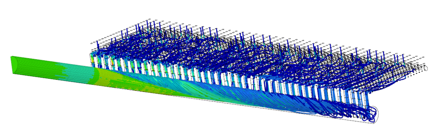
A significant vortex was also observed at the manifold outlet, at the transition to the submarine pipes, without the generation of internal recirculation zones. Streamlines showed a gradual reduction in density toward the end of the manifold, indicating a progressive evacuation of the flow.
- Head Losses:
- Nominal condition (524.45 m³/h): 0.069 bar
- Backwash condition (1139 m³/h): 0.384 bar
These losses are within acceptable margins and reflect efficient hydraulic behavior, with uniform flow distribution under both scenarios.
Conclusions
The CFD simulation enabled the effective redesign of the limestone filter manifold, achieving uniform flow distribution among the collectors and reducing the hydraulic imbalances present in the original design. Modifying the branch diameters, combined with detailed modeling, minimized head losses and eliminated critical flow zones. The optimized system meets the operational requirements under both nominal and backwash regimes, validating its applicability under real plant conditions.
At Engineering Simulation Consulting, we offer advanced engineering solutions to help companies optimize designs, improve performance, and reduce development costs. Contact us here to learn about our CFD simulation services for the hydraulic sector.


